Giacomini Balancing Systems
Effective control of a thermal system is only possible if the required flow-rates of the heat transfer fluid are available at the terminals: once the required flow-rates have been obtained, these must be measured and adjusted. This is why hydronic balancing is essential. The basic question is: how do you get correct balancing? The starting point is to get a proper flow distribution by dimensioning the plant carefully. This is true only in theory: in fact, heat generators, piping, pumps and terminals are designed to cover maximum demand. If a chain ring is not properly dimensioned, the others will not work optimally and consequently the desired indoor climate and comfort will not be achieved. Designing the plant with certain safety factors would prevent some of the problems, but would create other larger ones, especially on the control side. However, some over dimensioning cannot be avoided as components must be selected from existing business dimensions that typically do not match exactly the calculations made. Also, during design, the characteristics of some components are unknown as they are selected only during installation. Therefore, it would be necessary to modify the original system considering on-site installation, often different from the initial design. Hydronic balancing allows to obtain the required flow-rates in real installations, preventing over dimensioning and justifying the investment made.
Situation A
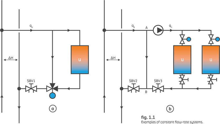
Constant flow-rate distribution systems.
In a constant flow-rate distribution system (fig. 1.1a), the three-way control valve is calculated to generate a pressure drop at least equal to the design pressure drop in terminal U. This means a control valve with an authority of at least 0.5, an essential value for proper regulation. Practically, the pressure drop on the control valve must be the same of the downstream pipe. If the pressure drop in the pipe, plus the pressure drop of the control valve, is 20 kPa and the differential pressure available (ΔH) is 80 kPa, then the 60 kPa difference must be removed from SBV1. Otherwise, this circuit will create a flow-rate that is 200 % that of the design flow. This situation will make control difficult and affect the rest of the system. In fig. 1.1b, SBV2 is essential. Without it, bypass AB will be a short circuit with an extreme overflow, creating underflows elsewhere in the plant.
With SBV2, the primary flow-rate qp is measured and set to be a bit bigger than the secondary design flow-rate qs , measured and set with SBV3. Balancing ensures correct flow-rate distribution, prevents operational problems and allows regulators to actually work without significant oscillations.
Situation B
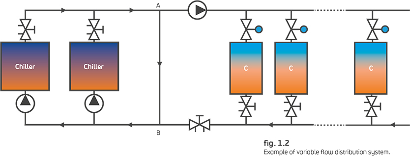
Variable flow-rate distribution systems
In a variable flow-rate distribution system, insufficient flow-rate problems occur basically when high loads are required.
In theory, there would be no justification for balancing a system with two-way control valves on the terminals, since these valves are designed to modulate the flow-rate to the required level. Hydronic balancing should therefore be obtained automatically. However, as soon as the proportional valves begin to close, the differential pressure can increase considerably, generating noise and regulation disturbances before the pump can react. Trying to avoid overflows this way will simply make the problem of an inadequate flow-rate worse: specific devices, i.e. differential pressure control valves (DPCVs), are specially designed to handle this situation. DPCVs set the differential pressure to a desired level. This level should be adequate to obtain the design flow-rate in the farthest pipes while not exceeding the maximum value associated with the valve/actuator combination (based on the maximum force of the actuator itself).
Situation C
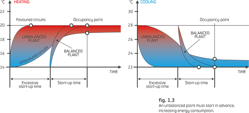
Start-up In variable flow-rate distribution systems
start-up after each shutdown represents a delicate operation as most control valves are activated while fully open. This situation generates overflows that cause excessive pressure drops in some parts of the pipeline network, while not supplying the terminals of less favored sections of the plant. Disadvantaged circuits will not reach a sufficient flow-rate until the privileged rooms have reached the thermostat set-point (assuming the set-point has been selected in a reasonable manner). This allows the control valves of said circuits to start working properly. Start-up is therefore difficult and takes longer than expected. This results in heavy energy consumptions. In addition, uneven start-up makes management by a central controller and any form of optimization practically impossible.
In a constant flow-rate distribution system, insufficient flow-rates and overflows both remain present during and after start-up, making the problem much more difficult.